Atomsk
The Swiss-army knife of atomic simulations

The Swiss-army knife of atomic simulations


This tutorial explains how to generate 3-D or 2-D polycrystals, containing grains of random or specific positions and orientations.
▶ For more information, refer to the corresponding documentation page.
The mode "--polycrystal", as its name suggests, aims at creating a polycrystal.
In the following examples, a unit cell of aluminium will be used as a seed. Such a unit cell can be generated with:
atomsk --create fcc 4.046 Al aluminium.xsf
Atomsk uses a Voronoi tesselation to construct polycrystals, as illustrated in the figure below.
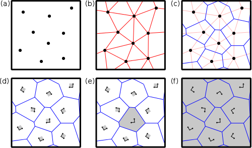
(a) Nodes (black dots) are introduced at given positions inside the simulation box.
(b) Nodes are linked with their neighbors (red lines). Periodic boundary conditions are used.
(c) The normal to the red lines are found (blue lines). These blue lines define the contours of the future grains, i.e. the grain boundaries.
(d) Atomic "seeds" (for instance unit cells) are placed at the positions of the nodes, with the given crystal orientation.
(e) A seed is expanded in the three directions of space. Atoms that are outside of the grain are removed.
(f) After all seeds have been expanded and cut inside their respective grains, one obtains the final polycrystal.
This illustrates the generation of Voronoi polycrystal in 2-D, but can be generalized to the 3-D case.
Let us start with a random polycrystal. Only two informations are needed: the dimensions of the final box, and the number of grains that it must contain. With this information, Atomsk will generate random positions for the nodes, and random crystal orientations for each grain.
First, the parameters must be written into a text file. For instance, to generate a polycrystal with 12 grains inside a box of size 200x200x200 Å3, create a file like this:
         box 200 200 200

         random 12
Then, run Atomsk in mode "--polycrystal", using "aluminium.xsf" as a seed and the text file created above:
atomsk --polycrystal aluminium.xsf polycrystal.txt final.cfg
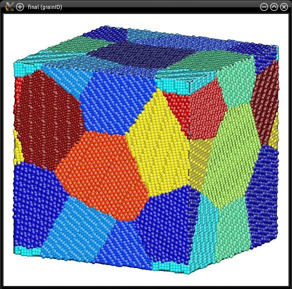
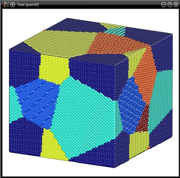
The final system is written into "final.cfg", in Atomeye CFG format. Atomsk creates a new auxiliary property named "grainID". This property indicates, for each atom, the grain index (here from 1 to 12). The generated polycrystal can then be visualized, e.g. with Atomeye (use Alt+0 to visualize the grainID):
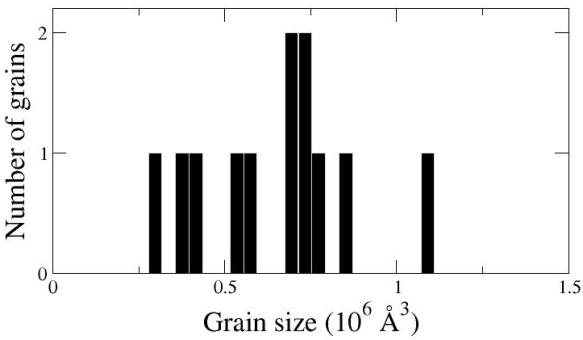
Atomsk also produces a data file (here "final.dat") containing the grain size distribution. It is a text file that may be opened with a text editor, or visualized as a graph:
It is important to note that "random" means that the numbers generated by Atomsk are different every time, and hence the generated polycrystal is different every time. If you try the command above, your polycrystal may look very different from the one in the picture. It will also be different every time you run the same command again.
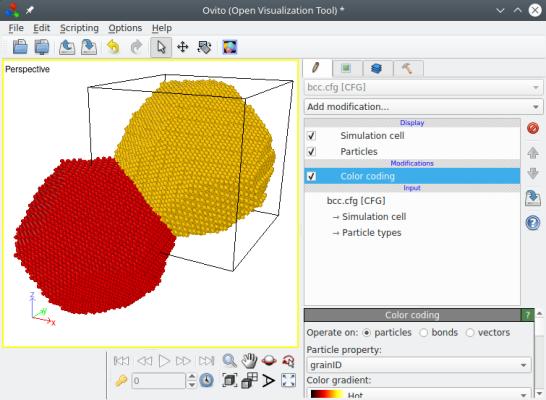
When constructing a polycrystal, the unit cells are expanded into their Voronoi polyhedra using Cartesian coordinates. So, after the generation of the polycrystal, some atoms may be located outside of the simulation box. You will realize that if you visualize the system e.g. with OVITO:
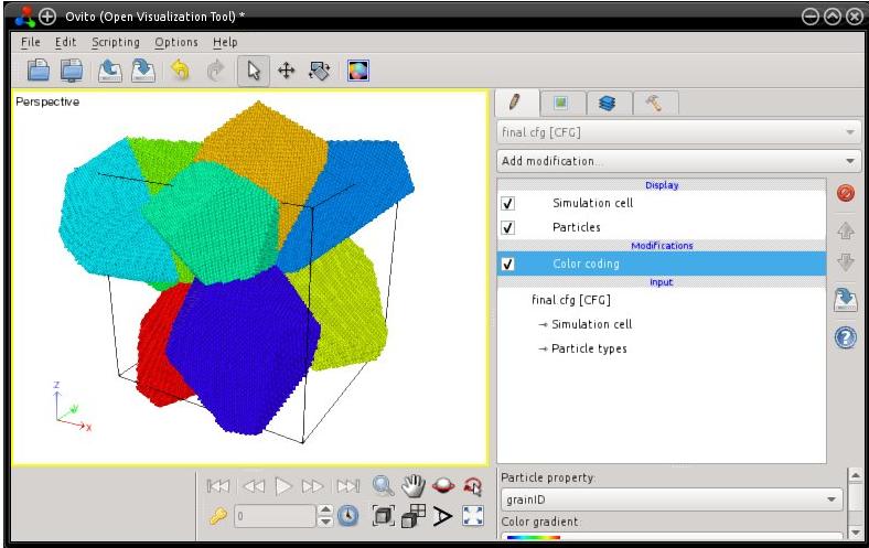
Note that many visualization software (like Atomeye) automatically wrap atoms, i.e. they always display atoms as if they were inside the box. But, if you open the file ("final.cfg") and look at the atom positions, you will find that some atoms are actually outside of the box. It is also recommended to read the tutorial about boundary conditions.
If you wish to apply periodic boundary conditions, so that all atoms are really inside of the box, then use the option "-wrap" when constructing the polycrystal, for instance:
atomsk --polycrystal aluminium.xsf polycrystal.txt final.cfg -wrap
Atomsk offers the possibility to place seeds at the positions of some pre-defined lattices. In this case the positions of the nodes will mimick those of the given lattice, and the crystal orientations inside the grains will be random.
To use this possibility, write the box dimension in the parameter file like before, and then write the keyword "lattice" followed by the lattice type: it can be "bcc", "fcc", "diamond", or "hcp". For example, to produce a polycrystal with a bcc arrangement, try the following:
         box 100 100 100

         lattice bcc
Then the polycrystal is constructed just as before:
atomsk --polycrystal aluminium.xsf polycrystal.txt bcc.cfg
You may visualize the final result "bcc.cfg" with OVITO. Below, the atom positions are represented as constructed by Atomsk on the left, showing that one grain is located at the origin and the other at the center of the box, thus imitating the sites of a bcc lattice. And on the right, atoms have been wrapped (i.e. put into the box) to show that those two grains fill the box completely.
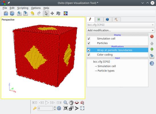
Some important points should be made here. First, the positions of the nodes imitate those of a bcc lattice, i.e. one node is placed at the origin (0,0,0), and the second one at the center of the box. The orientation of the aluminium crystals however, are decided randomly by the program. If you wish to have more control over the crystal orientations, please refer to section 5 below.
Second, the "lattice" used to place the seeds, has nothing to do with the actual atomic lattice of the material. In the example above, the atomic lattice of aluminium is fcc, and the polycrystal is constructed by placing nodes on a "bcc-like" lattice. In the end, each grain contains an aluminium crystal with the fcc atomic lattice.
Finally, if the box is not a square, then the seeds are still placed at the origin and at the center of the box, i.e. at the reduced coordinates (0,0,0) and (½,½,½). This will result in different grain shapes. You may try this by modifying the box size in the parameter file.
You may also try the other lattice types (fcc, diamond, hcp) and see what type of result you get.
Sometimes it is preferrable to control "manually" the positions and/or the orientations of the grains. Again the size of the final box must be given. Then, each grain must be defined with a line starting with the keyword "node", followed by the position of the grain (three real numbers) and its crystal orientation. For example:
         box 200 180 210

         node 0 0 0 [100] [010] [001]

         node 40 80 60 56° -83° 45°

         node 0.8*box 0.6*box 0.9*box [11-1] [112] [1-10]

         node 50 5 60 [110] [1-10] [001]

         node 0.75*box 0.3*box 0.45*box -31.4° 28.7° 90.0°

         node 60 100 80 random
Such a parameter file is interpreted as follows:
(1) The box will have dimensions 200 Å x 180 Å x 210 Å.
(2) The first grain will be positionned at the origin (0,0,0), and will be oriented X=[100], Y=[010], Z=[001].
(3) The second grain will be positionned at (40,80,60) (in Å), and the crystal will be rotated by 56° around the X axis, then -83° around Y, and then 45° around Z.
(4) The third grain will be positionned at the reduced coordinate (0.8,0.6,0.9). Note how the keyword "box" is used to specify reduced coordinates. This grain will be oriented X=[111], Y=[112], Z=[110].
(5) The last grain will be positionned at (60,100,80) (in Å), and will have a random orientation.
And so on. The various possible notations can be mixed up as in this example, but you may find it easier to use the same notation throughout your file. For instance specify all coordinates in Å (or all in reduced coordinates), and specify all orientations in degrees.
After generating your text file, run Atomsk with the same command as before:
atomsk --polycrystal aluminium.xsf polycrystal.txt final.xsf cfg
This time Atomsk will use the positions and orientations that you have specified, and the final polycrystal will look as follows:
Finally, Atomsk allows to construct 2-D polycrystals. To do so, simply set one box dimension to zero, as in the following example:
         box 200 200 0

         random 12
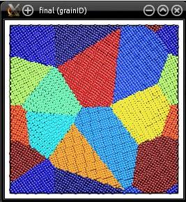
Atomsk will automatically replace the zero value by the actual size of the seed along that dimension. Here we use a unit cell of aluminium of lattice constant 4.046 Å as a seed, therefore Atomsk will automatically set the box dimension to 4.046 Å along the Z direction. Since the polycrystal is 2-D, all the grains will have their [001] axis aligned with the Z direction, and the grains will only be rotated around the Z axis. This is what the final system looks like:
As before, it is also possible to use the keyword "lattice" followed by "bcc", "fcc", "diamond", or "hcp". In the case of 2-D crystals, nodes will be placed according to a simple 2-D lattice.
Alternatively, it is also possible to specify the positions and orientations of the grains manually in a 2-D polycrystal. The usage is similar to what is explained in section 5 above. However, in the case of a 2-D crystal, make sure that all coordinates along the short direction are the same (e.g. set them all to 0), and provide a rotation only along the short axis (rotation along other axes will break the crystal symmetry along the short axis).
If you wish to have another crystal direction along the Z axis, then the original seed has to be oriented accordingly. For instance, the file "aluminium.xsf" used above should have the desired lattice orientation. You may follow this tutorial to learn how to generate oriented unit cells with Atomsk.
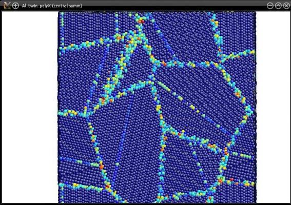
The seed does not have to be a unit cell: actually, any atomic system can be used as a seed. As an example, let us use the system containing a twin boundary "Al_final.cfg", constructed in a previous tutorial. Let us construct a random polycrystal with 12 grains (see the file "polycrystal.txt" in section 2 above):
atomsk --polycrystal Al_final.cfg polycrystal.txt Al_twin_polyX.cfg
In the end, each grain of the polycrystal will contain twins:
More generally, any atomic system can be used as a seed. You may try with an atomic system containing a dislocation (or many), or a stacking fault, or really just any atomic system you want.
The capability to construct 2-D polycrystals can be used to generate grain boundaries, as explained in the following tutorial.
Furthermore, it is possible to generate multi-phase polycrystals. Read this tutorial to know more.