Atomsk
The Swiss-army knife of atomic simulations

The Swiss-army knife of atomic simulations

This tutorial explains how to use Atomsk to construct systems with any arbitrary crystallographic orientation, using the mode "--create", and/or the options "-rotate", "-orthogonal-cell", and "-reduce-cell". It is recommended to be familiar with crystallography and Miller indexing to follow this tutorial.
▶ For more information, refer to the corresponding documentation page.
Crystal orientation can be a tricky concept as it requires a good 3-D representation of a crystal, its directions and planes, which can be confusing at first for students and beginners. For that reason, let us define clearly some key concepts. In a simulation, three different sets of vectors can be distinguished, and must not be confused with one another:
When constructing a unit cell of a cubic material, those three sets of vectors are basically identical: the crystal direction [100] is aligned with the X axis, the direction [010] with the Y axis, and [001] with Z, and the box vectors are exactly equal to the lattice vectors. This is often the representation made by textbooks, and it can cause confusion in the minds of beginners -like, as I have read sometimes, writing that [100] is the "X direction of the crystal", which can only lead to errors and misunderstandings.
It is imperative to differentiate these vectors and directions. First, the Cartesian axes X, Y, Z are defined by convention, i.e. they are chosen arbitrarily at the beginning of the problem, and never change afterwards. They represent the rigid and unmoveable metric of space, in the sense of Newton's absolute space: independent of time, and independent of what happens inside that space, whether or not you add atoms, rotate your crystal or whatever.
Then, inside this Cartesian space, the crystal axes point in directions that are defined by crystallography. It is possible to rotate the crystal, which will cause the crystal axes to change with respect to the (fixed) Cartesian directions. A crystal may have its [100] axis aligned with the Cartesian X axis, but that does not have to always be the case. For instance, one may rotate the crystal, so that the [110] crystal axis becomes aligned with the Cartesian X direction. Or, one may desire that the [111] axis of the crystal lies along the Cartesian Z direction, and so on. For the sake of brevity, the orientation of the crystal with respect to Cartesian directions is often noted with an equal sign, like X=[110], or Z=[111].
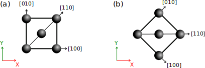
(a) By default, a unit cell of a perfect crystal (e.g. fcc) is created with its [100] crystal axis aligned with the Cartesian X direction, [010] aligned with Y, and [001] aligned with Z (the latter is not represented, it would point out of the figure).
(b) If the crystal is rotated by 45°, then it is the [110] crystal axis that becomes aligned with the Cartesian X axis. Note that the Cartesian frame (X,Y,Z) is defined by convention and does not change.
Finally, the vectors of the simulation box may also rotate, or be changed depending on one wants to achieve. As a simple example, if you start from a unit cell and duplicate it to form a supercell, then the crystal directions remain the same, but the box vectors change. Sometimes, one expects or desires that the box vectors are aligned with Cartesian axes. However in the most general case, the three vectors defining the simulation box can have any components along the Cartesian X, Y and Z axis (see the previous tutorial about boundary conditions). If one wants to maintain the crystal periodicity (so-called "periodic boundary conditions"), then the box vectors must be linear combinations of the crystal lattice vectors. Yet again, in the most general case, it does not always have to be the case, and sometimes it is not even possible to keep the periodicity (for instance if the crystal contains extended defects like dislocations).
In summary, when speaking about crystal orientation, one must have a clear representation of these different sets of vectors in mind, and not confuse them. In the following, you will learn how to orient crystals with respect to the Cartesian axes with Atomsk.
In a previous tutorial, you learned how to generate simple crystal lattices with Atomsk. Now, we will see how to choose a different crystal orientation. For that, after the parameters of the mode "--create", add the keyword "orient" and the three crystal directions (Miller notation) that you want along X, Y, and Z.
For instance, to create a copper fcc lattice with the crystal direction [110] along X, [110] along Y, and [001] along Z, run the following command:
atomsk --create fcc 3.597 Cu orient [110] [-110] [001] Cu.cfg
ⓘ Miller indices must be given as a single continuous string (no blank space between indices). Square brackets [] are optional and may be omitted, for instance "orient 110 -110 001". Miller indices with two (or more) digits must be separated by an underscore, for example: "10_-12_0".
An important thing to remember, is that the provided vectors must follow Miller's notation, and they must form an orthogonal basis. If vectors are not perpendicular to one another, Atomsk will display an error message and terminate. You may visualize the final system ("Cu.cfg") with OVITO:
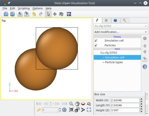
Atomsk has automatically used the given crystal directions as box vectors, so that the cell is orthogonal. When possible, Atomsk uses crystal symmetries to reduce the size of the box, in order to provide the smallest unit cell possible. In the fcc lattice, the shortest lattice vector along a given [hkl] direction is actually ½[hkl] when one Miller index is odd and the other two are even. In the example above, one might expect the box to have a length of 3.597√2 = 5.087 Å along the [110] direction. Instead, Atomsk reduces it by half. The goal is to provide the smallest unit cell respecting the given crystal orientation. In this orientation, the unit cell counts two atoms as you can see in OVITO.
Atomsk supports this method for all cubic crystal lattices, and other directions. For instance, let us create an oriented lattice of iron so that X=[121], Y=[101] and Z=[111]:
atomsk --create bcc 2.85 Fe orient [121] [-101] [1-11] Fe.xsf
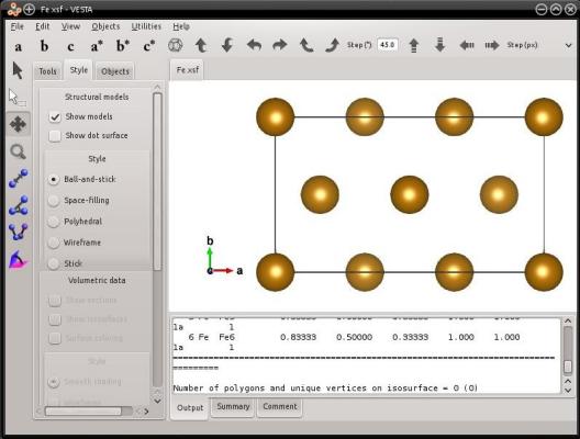
Just as before, Atomsk takes advantage of the symmetries of the bcc lattice to reduce the size of the cell. In the bcc lattice, the period along a [hkl] direction is reduced to ½[hkl] when all three Miller indices are odd. In this example, it is the case for the [111] direction. In this orientation the unit cell of iron counts 6 atoms.
The mode "--create" allows to generate many cubic lattices (including diamond, zincblende, perovskite...). As an exercise, you may try to generate and orient any of them.
Atomsk can now orient hexagonal lattices during their creation: hexagonal close-packed (hcp), wurtzite, and graphite. However, "crystal orientation" means something different from the cubic lattices.
For the sake of example, let us create a unit cell of magnesium with the hcp lattice. When generating a hcp lattice with the mode "--create", the box vectors follow the hexagonal lattice, hence one box vector (the second one in this case) is not aligned with a Cartesian axis:
atomsk --create hcp 3.21 5.213 Mg Mg.xsf
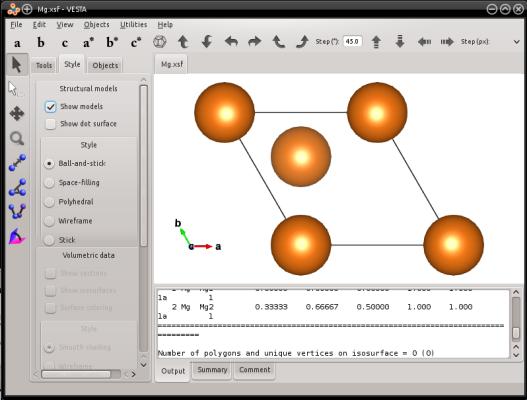
As you may know, in an hexagonal lattice the crystal directions are referred to using four Miller indices [hkil], that must satisfy h+k+i=0 (if you are not familiar with this notation, please refer to a book of crystallography). For hexagonal lattices, you may use the keyword "orient" followed by three crystal vectors [hkil]. Atomsk will use these vectors to create a box, and fill it with atoms. Then, the first box vector will be aligned with the Cartesian X axis, the second box vector will be placed in the XY plane, and the third box vector will point out of the XY plane.
Let us construct an oriented hcp crystal of magnesium:
atomsk --create hcp 3.21 5.213 Mg orient [0-110] [0001] [2-1-10] xsf
These vectors happen to be orthogonal, so the [0110] crystal direction will be aligned with the Cartesian X axis, [0001] with Y, and [2110] with Z. The cell will look like the following:
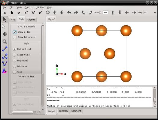
However, in the case of hexagonal lattices, the provided Miller vectors do not have to be orthogonal. It is possible to provide any crystal direction of the hexagonal lattice, and Atomsk will create a box with the provided vectors. This can be illustrated with the following example:
atomsk --create hcp 3.21 5.213 Mg orient [0-110] [10-10] [0001] xsf
In this example, the hexagonal directions [0110] and [1010] are not orthogonal. Atomsk will create a box where the first box vector H1 will be [0110] and aligned with the Cartesian X axis; the second box vector H2=[1010] will be in the Cartesian XY plane (note that it is NOT aligned with the Cartesian Y direction); and the third box vector H3=[0001] will point out of the XY plane (in this particular example, [0001] is aligned with Z, but it does not have to be the case). In the end, the system will look like the following:
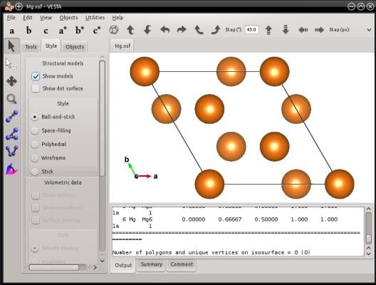
This way, it is possible to create hexagonal cells where the 3-fold symmetry is still apparent. You may try similar commands, using the hexagonal graphite or wurtzite lattice.
It is important to understand that, contrary to cubic systems, oriented hexagonal systems do not necessarily form an orthogonal box. In the case of hexagonal systems, the crystal directions that you provide are not necessarily aligned with Cartesian directions; they serve to define the box vectors. If you wish to obtain an equivalent orthogonal cell for such a box, you may use the option "-orthogonal-cell", as explained in section 4 below.
In the most general way, a rotation is a transformation that modifies the crystal directions that are along the Cartesian axes X, Y and Z. For instance, one may use the option "-rotate" to rotate a crystal:
atomsk initial.xsf -rotate Z 33 final.xsf
In this case, depending on the rotation axis and angle, different crystal directions can be aligned with the Cartesian axes. This requires to know exactly how to rotate the crystal.
However the option "-rotate" can be quite cumbersome to use, if one desires to obtain a non-simple crystal orientation. For more complex rotations, one may use the option "-orient" (not to be confused with the keyword "orient" that belongs to the mode "--create", as discussed before). For instance, assume that you have a (non-oriented) unit cell of iron, generated with the following:
atomsk --create bcc 2.85 Fe Fe.xsf
You may use the option "-orient" to rotate it into another orientation. This option requires that you provide the current crystal orientation (3 vectors using Miller notation), followed by the target crystal orientation (3 other vectors, still using Miller notation). Here, the initial orientation of the iron unit cell is simply [100] along X, [010] along Y, and [001] along Z. Let us rotate this crystal so that the [121] direction lies along the Cartesian X axis, the [101] along Y, and [111] along Z:
atomsk Fe.xsf -orient [100] [010] [001] [121] [-101] [1-11] Fe_orient.cfg
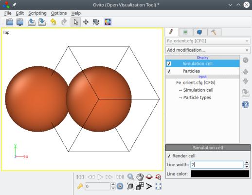
When you open this file for visualization in OVITO, notice the Cartesian reference (x,y,z) displayed at the bottom left. As you can see, the option "-orient" rigidly rotates the whole system, box and atoms together. As a result, the box vectors are not aligned with the Cartesian axes anymore: each box vector has components along X, Y and Z.
This is another fundamental point to keep in mind: just because you rotate an atomic system, does not mean that the box vectors will "magically" be re-calculated and become orthogonal. Each box vector can rotate, and have any arbitrary components (x,y,z). As such, Atomsk can work with three box vectors that may have any (x,y,z) components, and rotate them arbitrarily. Note that this is not true for all softwares: some visualization or simulation softwares have restrictions about the box vectors that they can handle.
If you wish to keep a given crystal orientation, and obtain an orthogonal box that is aligned with Cartesian directions, then proceed with section 4 below.
To obtain an orthogonal cell from any arbitrary atomic system, another method is available within Atomsk: the option "-orthogonal-cell". This option takes any box vectors as input (even if they are non-orthogonal, or if they are not aligned with Cartesian axes). Then, it tries to find the best linear combinations of the box vectors that produce a new set of vectors that are perfectly aligned with the Cartesian X, Y and Z axes. These new vectors define a new box, which is orthogonal. Then, atoms are duplicated so as to fill this new box. In the end, one obtains an orthogonal box that is equivalent to the initial system, and respects the lattice periodicity.
This option can be used after rotating a crystal by any arbitrary angle. To illustrate how it works, let us decompose the steps. First, create a unit cell of fcc copper and rotate it by -45° around the Cartesian Z axis:
atomsk --create fcc 3.597 Cu -rotate Z -45 Cu_rotated.cfg
Visualization shows you that the whole system (box+atoms) was indeed rotated, just as explained in section 3 above:
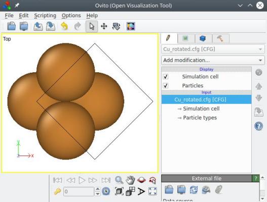
So now, the [110] direction lies along the Cartesian X axis, and [110] along Y (the [001] crystal direction, being the rotation axis, still lies along Z). However, the box vectors are not aligned with Cartesian directions. To achieve that, one can use the option "-orthogonal-cell" (this option does not take any parameter):
atomsk Cu_rotated.cfg -orthogonal-cell Cu_ortho.cfg
After applying this option, the crystal orientation is preserved (i.e. the [110] direction is still along X, and so on), but now the three box vectors are also aligned with the Cartesian X, Y and Z directions, respectively. Furthermore, atoms were duplicated so as to fill this new box, so the number of atoms in the system is different:
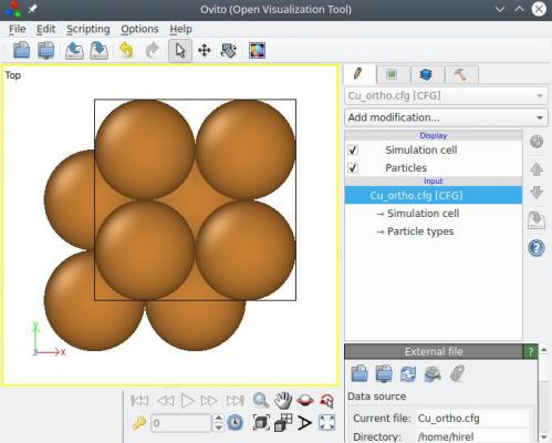
Contrary to the method explained in the first section above, the option "-orthogonal-cell" does not use crystal symmetries to reduce the cell size. So, this time, the final cell has the size of a full <110> vector along X and Y, i.e. 3.597√2 (and not half of it). This is because the option "-orthogonal-cell" ignores completely the lattice type, hence it is not aware of symmetries that would allow to reduce the cell size. If you wish to reduce the cell size, you may use the option "-reduce-cell" afterwards (see next section).
By the way, all the steps above may be achieved in a single Atomsk command:
atomsk --create fcc 3.597 Cu -rotate Z -45 -orthogonal-cell Cu_ortho.cfg
Of course, for cubic lattices this method is quite heavy, and the method described in the first section above is more appropriate. The point of the option "-orthogonal-cell" is that it allows to orient any type of system, which makes it very powerful and useful for non-cubic lattices.
As explained in the previous section, the option "-orthogonal-cell" is not aware of the possible symmetries of the crystal. As a result, the cell obtained ("Cu_ortho.cfg") is properly oriented, but it is not the smallest possible cell corresponding to that orientation. Just looking at it in OVITO, one can guess that it can be reduced by half along X and Y.
Atomsk offers the option "-reduce-cell", which attempts to reduce the size of a cell while preserving the crystal periodicity. For that, it searches for equivalent atoms along each box direction, and detects the shortest vector joining two equivalent atoms.
atomsk Cu_ortho.cfg -reduce-cell Cu_unitcell.cfg
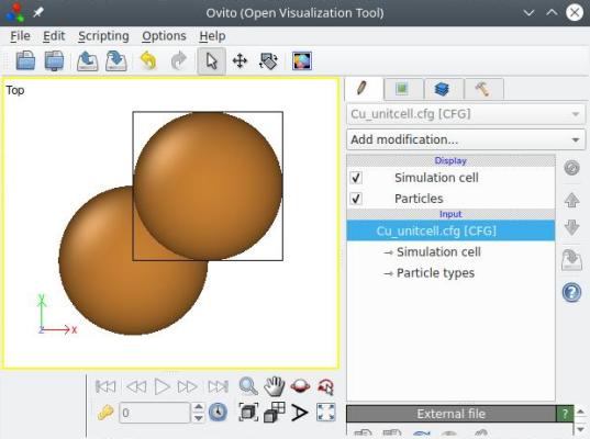
With that, the system is down to 2 atoms, which is the smallest orthogonal cell one can obtain for this crystal orientation. Again, all the previous options can be called in a single command-line:
atomsk --create fcc 3.597 Cu -rotate Z -45 -orthogonal-cell -reduce-cell Cu_unitcell.cfg
Let us make a magnesium hcp lattice into an orthogonal cell. Just like in section 2 above, we obtain a unit cell where the second vector is not aligned with a Cartesian axis:
atomsk --create hcp 3.21 5.213 Mg Mg.xsf

Now, if we use the option "-orthogonal-cell" on this system, we can obtain an equivalent lattice with an orthogonal box:
atomsk --create hcp 3.21 5.213 Mg -orthogonal-cell Mg_ortho.xsf
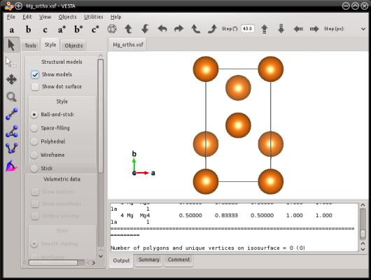
This is exactly the same hexagonal lattice, with the same crystal orientation. The only thing that changed is that other lattice vectors were used, to make the box orthogonal. This way, the periodicity of the lattice is preserved. The only thing that is different is that the three box vectors are now perpendicular with each other. Also, atoms have been added in their equivalent lattice sites, so as to fill this new box.
Now, this option can also be useful with oriented hexagonal lattices. As explained in section 2 above, when creating an oriented hexagonal lattice, the box is not automatically made orthorhombic. But you can make it so, using the option "-orthogonal-cell". Let us try with the same example as in section 2 above, but adding the option "-orthogonal-cell":
atomsk --create hcp 3.21 5.213 Mg orient [0-110] [10-10] [0001] -orthogonal-cell xsf
The final system is indeed contained in an orthogonal box:
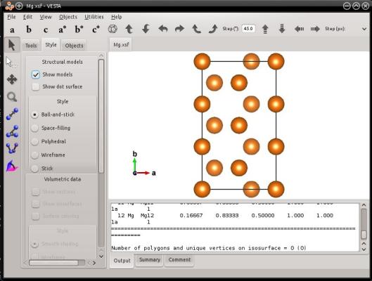
A warning should be written here, as the command above and the visualization may be confusing. In this example, the [1010] crystal direction is NOT aligned with Y! As explained in section 2, this crystal direction was used to create the initial cell (see the same command without the option "-orthogonal-cell", in section 2 above). After running the option "-orthogonal-cell", the box vectors changed, so that the [1010] crystal direction is not aligned with a cell vector anymore, neither with a Cartesian axis. If you want to know which crystal direction is aligned with the Cartesian Y axis, then you have to determine it yourself. So, be careful when using the option "-orthogonal-cell", and again, do not confuse Cartesian directions, box vectors, and crystal directions.
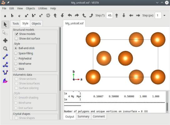
Optionally, you may use the option "-reduce-cell" to obtain a shorter cell:
atomsk --create hcp 3.21 5.213 Mg orient [0-110] [10-10] [0001] -orthogonal-cell -reduce-cell Mg_unitcell.xsf
The final system is indeed contained in an orthogonal box:
Instead of the above, you may also rotate the system by any arbitrary angle with the option "-rotate", and then use the option "-orthogonal-cell". For instance, we can determine that rotating the hcp crystal by -30° around the Cartesian Z direction aligns the [1120] crystal axis with X. Then, we can use the option "-orthogonal-cell" to obtain an equivalent orthogonal box:
atomsk --create hcp 3.21 5.213 Mg -rotate Z -30 -orthogonal-cell Mg_110.xsf
Thus, by applying the appropriate rotations and then using the option "-orthogonal-cell", you may obtain an orthogonal cell with the crystal orientation that you desire. After that, you may duplicate this cell (with the option "-duplicate") to obtain a supercell, and further design your atomic system.
After applying the option "orthogonal-cell", the final cell may be very large and contain a lot of atoms (sometimes more than a thousand). As explained before, this is because Atomsk only searches linear combinations of the initial box vectors, and does not know if a shorter lattice vector can be found along particular directions. In some cases, it may be possible to reduce the size of the cell produced by this option, but you will have to do it "manually". It can be achieved by removing atoms above a given plane with the option "-cut" (see this tutorial), and then change manually the box size in the final text file.
In some cases, the option "-orthogonal-cell" may fail to find a suitable orthogonal box, typically when some box vectors form a very acute angle, or have lengths that are incommensurate. In such cases, it may help to use the option "-unskew" to reduce the tilt of the box before using the option "-orthogonal-cell". However, if Atomsk still fails to find an orthogonal box, then you may have to think of another way to construct your system or to perform your simulation.
The option "-reduce-cell" is designed for perfect crystals, and should work in most cases. However it cannot be expected to produce correct results for defective systems (containing vacancies, defect clusters, dislocations...), nor for molecular systems.