Atomsk
The Swiss-army knife of atomic simulations

The Swiss-army knife of atomic simulations


This tutorial explains how to construct a ⅓[111] partial Frank dislocation loop in aluminium. It is recommended to be familiar with the theory of dislocations in order to follow the steps below.
▶ For more information, refer to the corresponding documentation page.
ⓘ This tutorial is about climb dislocation loops, i.e. where the Burgers vector is normal to the plane of the loop. For glide dislocation loops, refer to this tutorial.
As in previous tutorials, the supercell must have the appropriate crystal orientation. In addition, it must be large enough along all directions to host a dislocation loop:
atomsk --create fcc 4.046 Al orient [11-2] [111] [-110] -duplicate 20 14 30 Al_supercell.xsf
We wish to introduce a partial Frank dislocation loop, of Burgers vector b=⅓[111], in a (111) plane. With the orientation that we have chosen, the Cartesian coordinates of the Burgers vectors will be b = (0 by 0), where by = a0×√3/3 ≈ 2.336 Å.
ⓘ For this type of dislocation loop, the Burgers vector b is normal to the plane of the loop. In our example, the loop plane is normal to Y, so b is also along Y.
As a first naive approach, a Frank partial dislocation can be obtained by removing a disc of atoms in a (111) plane. This can be achieved with Atomsk, by combining several selections. First, select all atoms inside a cylinder of the chosen radius, aligned with the Cartesian Y direction, so that the cylinder axis is normal to the (111) plane. Then, remove from this selection atoms that are below a coordinate ymin, and atoms that are above ymax. Make sure that ymax-ymin is equal to the magnitude of the Burgers vector by, so that only one (111) plane remains selected. In the example below we set ymin = 50 Å and ymax = 52.336 Å. Finally, once this selection is set, delete the selected atoms:
atomsk Al_supercell.xsf \
-select in cylinder Y 0.5*box 0.5*box 20 \
-select rm below 50.0 Y \
-select rm above 52.336 Y \
-remove-atoms select \
loop1.cfg
ⓘ The option "-select" is used here to select and un-select atoms. This option in itself does not actually delete atoms, it only adds or remove atoms from the selection. Only the option "-remove-atoms" actually deletes atoms. To learn more, refer to this tutorial.
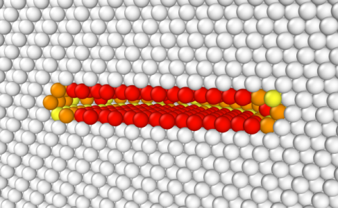
You may open the final CFG file with OVITO. In the figure below, atoms are coloured according to their centrosymmetry parameter (white atoms are in perfect environment, coloured atoms are not), and atoms in the bottom half of the box along Z are not displayed to facilitate the view (system was "cut in half" in OVITO). We can see that removing a platelet leads to the formation of a void inside the material, which is not very realistic, but can serve as a starting point for a simulation.
Instead of removing "manually" a platelet of atoms, you can rely on the option "-dislocation loop" of Atomsk. Let us place the loop at the center of the box (0.5*box along each direction), normal to the Y axis, and set the loop radius to 14 Å. Contrary to the previous tutorial, this time we give the Burgers vector only a Y component, i.e. the Burgers vector is b = (0 by 0). Finally, we use a Poisson ratio of 0.33, a typical value for aluminium:
atomsk Al_supercell.xsf \
-dislocation loop 0.5*box 0.5*box 0.5*box Y 14 0 -2.336 0 0.33 \
loop2.cfg
ⓘ A negative value of the Burgers component means that atoms are removed. This loop is sometimes referred to as a negative Frank loop, a vacancy loop, an intrinsic stacking fault, or an S-Frank partial dislocation (the S means that there is a Single stacking fault).
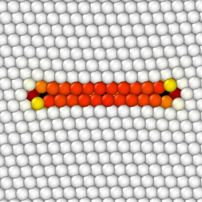
Atomsk removes atoms inside the loop, and then applies displacements due to the dislocation to all atoms. So, contrary to the previous section (removing a platelet), this time there is no void in the material.
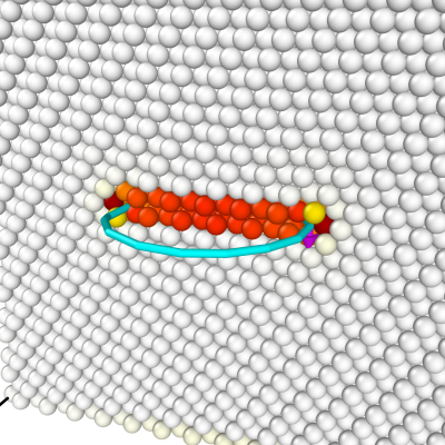
Again we open the final CFG file with OVITO, and colour atoms according to their centrosymmetry criterion. In addition, the dislocation analysis algorithm (DXA) is used to have a coarsed view of the dislocation line (make sure to choose the FCC lattice). This algorithm finds a partial Frank dislocation (cyan line), as expected.
Using the same command, changing only the sign of the by component of the Burgers vector, we can construct a positive Frank loop:
atomsk Al_supercell.xsf \
-dislocation loop 0.5*box 0.5*box 0.5*box Y 14 0 2.336 0 0.33 \
loop3.cfg
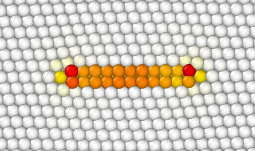
ⓘ A positive value of the Burgers component means that a new plane of atoms is introduced. This is also known as an interstitial loop, an extrinsic stacking fault, or a D-Frank partial dislocation (the D means that there is a Double stacking fault).
This time, atoms within the loop are duplicated, and then elastic displacements are applied to all other atoms.
As in the previous tutorials, when introducing dislocation loops one must be very careful about the Burgers vector, the plane, and the position of the loop. Do not hesitate to try different supercell sizes, different positions and radius of the loop. If some points of the loop are out of the box, Atomsk will display a warning. Note that the option "-dislocation" does not use periodic boundary conditions, so if some points of the loop are out of the box, they will not be wrapped or anything: they will be completely out of the system.
Finally, just like for straight dislocations, the dislocation loop introduced here is not relaxed nor optimized. However it may be useful as input for a simulation. Frank partial dislocation loops are expected to be sessile, however depending on various conditions they may dissociate into other types of dislocations. If you are unsure about how to proceed, please refer to a book about dislocations to learn more.