Atomsk
The Swiss-army knife of atomic simulations

The Swiss-army knife of atomic simulations


This tutorial explains how to construct dislocations in an anisotropic medium, using iron as an example. It is recommended to be familiar with dislocations and with anisotropic elasticity in order to follow the steps below.
▶ For more information, refer to the corresponding documentation page.
In previous tutorials, you learned how to construct dislocations of edge and screw characters. This method assumes isotropic elasticity, for which the deformation due to the dislocation depends only on the Burgers vector, and not on the elastic properties of the material (for edge dislocations only the Poisson ratio is needed).
When the material is anisotropic, the displacements due to a dislocation differ from the isotropic case, and the elastic constants have a major role to play. In order to perform simulations in such materials, it is often desirable to start with a configuration with the appropriate displacements.
For the sake of this tutorial, we will introduce dislocations in α-iron with the bcc structure, which is an anisotropic material. It is known that the most common dislocations in this material have a Burgers vector ½⟨111⟩.
The first thing to determine is the character (edge, screw, mixed) and the Burgers vector of the dislocation that you want to study. Then, you have to figure out the crystal orientation that is appropriate to study that dislocation.
We begin with the construction of a screw dislocation. Assume that we want the dislocation line (and also the Burgers vector) aligned with the Z axis, i.e. the crystallographic direction will be Z=[111]. The other two Cartesian directions must be perpendicular to Z, so we choose X=[121] and Y=[101].
In order to generate a unit cell with this orientation, you may use:
atomsk --create bcc 2.856 Fe orient [121] [-101] [1-11] xsf
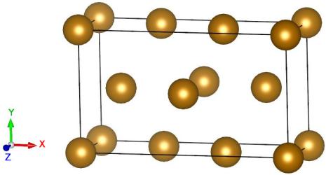
This is practical to have a first visualization of the oriented unit cell.
Because we want to use anisotropic elasticity to construct the dislocation, first we must provide the elastic constants of α-Fe to Atomsk. The first question to ask yourself is the following: what values of the elastic constants do I have to provide? Surely we will use values from the literature, but several different values exist out there, either determined experimentally, or from ab initio calculations, or from force-field simulations. Which one should be used?
As a rule of thumb: use the values that correspond to the model you are using. If your goal is to perform ab initio calculations, then use elastic constants that correspond to your pseudopotential and approximations. If you wish to simulate iron using a force-field, then use the elastic constants produced by the force field. This will get you closer to the stable state, and also minimize spurious stresses, especially if using fixed boundary conditions.
After choosing a set of elastic constants, write the full tensor into a text file (values below are just given as an example, and lines starting with the # symbol are comments and can safely be removed):
         # Full 6x6 elastic tensor for alpha-Fe (GPa)

         elastic

         243.30 145.00 145.00   0.00   0.00   0.00

         145.00 243.00 145.00   0.00   0.00   0.00

         145.00 145.00 243.00   0.00   0.00   0.00

           0.00   0.00   0.00 119.00   0.00   0.00

           0.00   0.00   0.00   0.00 119.00   0.00

           0.00   0.00   0.00   0.00   0.00 119.00
Alternatively, since α-iron is an orthotropic material, it is possible to use the shorter Voigt notation. The text file then looks like the following:
         # Elastic constants for alpha-Fe (GPa)

         elastic Voigt

         243.30 243.30 243.30   # C11 C22 C33

         145.00 145.00 145.00   # C23 C31 C12

         119.00 119.00 119.00   # C44 C55 C66
Now, the problem is that this elastic tensor is that of unoriented α-Fe, i.e. it corresponds to the crystal orientation X=[100], Y=[010], Z=[001]. Here we want to construct a system with a different orientation, which requires to rotate the elastic tensor. With Atomsk, one can simply specify the target crystal orientation, and Atomsk will automatically rotate the elastic tensor to match this orientation:
         # Elastic constants for alpha-Fe (GPa)

         elastic Voigt

         243.30 243.30 243.30   # C11 C22 C33

         145.00 145.00 145.00   # C23 C31 C12

         119.00 119.00 119.00   # C44 C55 C66


         # Actual crystal orientation

         orientation

         [121]

         [-101]

         [1-11]
Note that the section "orientation" must appear after the section "elastic" for the elastic tensor to be rotated accordingly.
atomsk --create bcc 2.856 Fe orient [121] [-101] [1-11] \
-duplicate 20 30 1 \
-prop elastic.txt \
-disloc 0.501*box 0.501*box screw z y 2.47336855321 \
Fe_dislo.cfg
This one-liner generates completely the system with the dislocation in it. Atomsk will first create the unit cell of bcc Fe with the required orientation (thanks to the mode "--create"), then duplicate it to generate a supercell, then read the elastic tensor from the file "elastic.txt", and then introduce the screw dislocation. Because the elastic tensor is provided, the dislocation will be introduced using anisotropic elasticity.
ⓘ The position of the dislocation can be given as fraction of the box vectors like above ("0.51*box"), or directly in Angströms. The given position should not correspond exactly to an atom position, otherwise that atom would have an infinite displacement. If you obtain strange results like discontinuities, holes or large displacements, then change the position of the dislocation.
Because the Burgers vector is ½[111], its magnitude is a√3/2, that is b=2.47336855321 Å. Note that the value of the Burgers vector has to be very accurate. Atomsk will not make any adjustments, nor try to guess the "best" value of the Burgers vector for you.
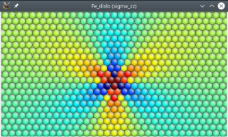
Atomsk computes the theoretical stress due to the dislocation, which are also computed using the anisotropic theory:
σij = ℜ{ (-2πi)-1 ∑(n=1,3) Bijk(n) Ak(n) D(n) / (x1+P(n)x2) }
The final output file "Fe_dislo.cfg" can be opened with Atomeye or OVITO. Within these softwares, the components of the theoretical stresses σxx, σyy, σzz, etc. can be visualized. As an example, the component σzz should look like the following:
Similarly to the screw dislocation in aluminium, it is possible to restore the periodicity of the system along the direction of glide (i.e. along X) by adding a Z component equal to b/2 to the first vector of the box.
Similarly, one can construct a dislocation with an edge character instead of screw. Two things must be taken care of. First, assuming that the dislocation line lies along Z as before, then the crystal orientation must be changed: we will use X=[111], so that the Burgers vector b=[111] is along X and normal to the dislocation. The glide plane remains the same, normal to Y=[101], and finally we must have Z=[121]. As a result, the file containing the elastic constants must be changed to contain the correct orientation:
         # Elastic constants for alpha-Fe (GPa)

         elastic Voigt

         243.30 243.30 243.30   # C11 C22 C33

         145.00 145.00 145.00   # C23 C31 C12

         119.00 119.00 119.00   # C44 C55 C66


         # Actual crystal orientation

         orientation

         [1-11]

         [-101]

         [121]
Second, the command-line itself must be modified in two places. The parameters of the mode "--create" must be modified to match the crystal orientation described above. In addition, the option "-dislocation" must be modified with the keyword "edge", and the Poisson ratio must be added in the end (this is similar to the isotropic case). However, since the elastic tensor is given in full, Atomsk does not use the value of the Poisson ratio, so you can set it to anything (here we just set it to zero). In the end the command-line looks like the following:
atomsk --create bcc 2.856 Fe orient [1-11] [-101] [121] \
-duplicate 20 30 1 \
-prop elastic.txt \
-disloc 0.501*box 0.501*box edge z y 2.47336855321 0.0 \
Fe_edge.cfg
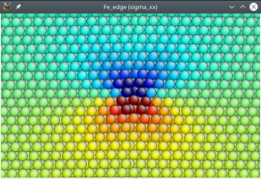
This time the final system will look like the following, where atoms are coloured according to the theoretical value of σxx, also computed by Atomsk using anisotropic theory:
The use of anisotropic elasticity (i.e. when an elastic tensor is provided) allows to construct mixed dislocations. Again, assuming we want a mixed dislocation with the same Burgers vector as before, the crystal orientation must be changed. The glide plane remains normal to Y=[101]. To keep the model simple, we choose X=[010] and Z=[101], so that the Burgers vector is simply:
b = ½[010] + ½[101] = ½[111]
To build this system, the text file "elastic.txt" must be modified like this:
         # Elastic constants for alpha-Fe (GPa)

         elastic Voigt

         243.30 243.30 243.30   # C11 C22 C33

         145.00 145.00 145.00   # C23 C31 C12

         119.00 119.00 119.00   # C44 C55 C66


         # Actual crystal orientation

         orientation

         [0-10]

         [-101]

         [101]
The command-line must also be modified to reflect the crystal orientation. In addition, the option "-dislocation" must contain the keyword "mixed" (instead of "screw" or "edge" before), and the three Cartesian components of the Burgers vector bx, by, bz, must be given in angströms. Here the components must be bx=a0/2 and bz=a0/√2 (the Burgers vector is contained in the glide plane normal to Y, so by=0). The command-line is then the following:
atomsk --create bcc 2.856 Fe orient [0-10] [-101] [101] \
-duplicate 20 30 1 \
-prop elastic.txt \
-disloc 0.501*box 0.501*box mixed z y 1.428 0.0 2.019496967 \
Fe_mixed.cfg
Opening the final file "Fe_mixed.cfg" in OVITO and triggering the dislocation analysis (DXA), we can verify that this dislocation is indeed of type ½⟨111⟩, and that the Burgers vector is inclined with respect to the dislocation line, as expected with a mixed dislocation:
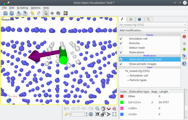
It is possible to construct mixed dislocations where the Burgers vector forms any arbitrary angle with respect to the dislocation line. You may try other orientations as an exercise.
Just like the isotropic case, you should keep in mind that the dislocations constructed above are not fully relaxed. The theoretical stresses computed by Atomsk, and visualized in Atomeye, are not the real stresses of an actual dislocation. The purpose is to construct a dislocation that is close to its equilibrium state, in order to perform an atomic-scale calculation (either ab initio or with empirical potential).
The simulation setup as constructed above does not allow for 3-D periodic boundary conditions. Introducing a dislocation produces displacements of all atoms, so that the opposite sides of the simulation box do not match anymore. After introducing a dislocation, the system is periodic only along the dislocation line.