Atomsk
The Swiss-army knife of atomic simulations

The Swiss-army knife of atomic simulations


This tutorial explains how to construct a ½[110] screw dislocation in aluminium. It is recommended to be familiar with the theory of dislocations in order to follow the steps below.
▶ For more information, refer to the corresponding documentation page.
Aluminium is a face-centered cubic (fcc) metal, where the most favorable slip system is of the type ½⟨110⟩{111}. We want to construct a system containing only one screw dislocation, lying along the Cartesian Z axis, of Burgers vector b=½[110], in a {111} plane normal to the Y axis, as shown in the schematic illustration below:
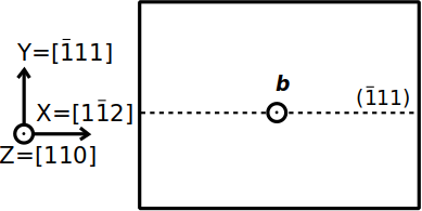
Based on this, we can define the crystal orientation. The Burgers vector of the screw dislocation is aligned with the dislocation line, so the crystal [110] direction must be aligned with the Cartesian Z axis. The slip plane is normal to the Y axis, so we must have Y=[111]. As a result we have X=[112]. Let us construct this supercell, assuming a lattice parameter a=4.046 Å:
atomsk --create fcc 4.046 Al orient [1-12] [-111] [110] -duplicate 40 20 1 Al_supercell.xsf
The Burgers vector ½[110] has a magnitude |b|=a/√2, which is about 2.860954 Å for the lattice parameter that we chose. Naturally, if you work with a different lattice parameter, then you have to compute the magnitude of the Burgers vector.
The screw dislocation can be introduced with Atomsk by using the option "-dislocation", followed by the position of the dislocation in the XY plane (here it is placed at the center of the box), the keyword "screw", the line direction (Z), the normal to the glide plane (Y), and the magnitude of the Burgers vector:
atomsk Al_supercell.xsf -dislocation 0.51*box 0.501*box screw Z Y 2.860954 Al_screw.xsf cfg
ⓘ The value of the Burgers vector must be given accurately, and must be consistent with the lattice parameter of your crystal. Atomsk will not "automagically" adjust this value.
ⓘ The position of the dislocation can be given as fraction of the box vectors like above ("0.51*box"), or directly in Angströms. The given position should not correspond exactly to an atom position, otherwise that atom would have an infinite displacement. If you obtain strange results like discontinuities, holes or large displacements, then change the position of the dislocation.
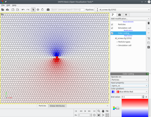
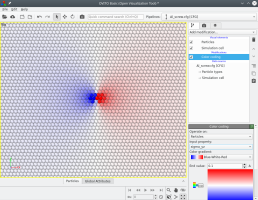
Atomsk computes the theoretical stress components (from elasticity theory), which can be visualized with Atomeye. For instance the image below shows the stress components σxz and σyz:
When introducing screw dislocations, the number of atoms remains constant. The system remains periodic along the dislocation line (here the Z direction), however the atoms displacements due to the dislocation break the periodicity of the lattice along both the X and Y directions. This can be dealt with in several ways:
ⓘ Atomsk does not apply any of these particular solutions automatically, therefore the user (you) has to explicitely apply one of them after introducing the screw dislocation.
It is possible to recover the periodicity of the lattice along the direction of glide (i.e. along the X direction in the current example). Indeed, at the edge of the supercell, atoms are displaced along Z by +b/2 above the glide plane, and -b/2 below the glide plane. Therefore, adding a Z component equal to b/2 to the first supercell vector restores the periodicity along the glide direction. This can easily be done with the option "-cell" that allows modifying cell parameters:
atomsk Al_screw.xsf -cell add 1.430477 zx Al_screw_cell.cfg
Alternatively, you may also change the value manually in the final file, at the condition that it contains atom positions in Cartesian coordinates, like XCrySDen XSF files or LAMMPS data files (and not reduced coordinates, like e.g. CFG files). For instance, in a XSF file, modify the third value in the first vector (here displayed in bold characters):
          # Fcc Al oriented X=[1-12] Y=[-111] Z=[110].

          CRYSTAL

          PRIMVEC

          198.21270999        0.00000000        1.43047700

            0.00000000      140.15755135        0.00000000

            0.00000000        0.00000000        2.86095404

          CONVVEC

          198.21270999        0.00000000        1.43047700

            0.00000000      140.15755135        0.00000000

            0.00000000        0.00000000        2.86095404

         PRIMCOORD

         (...)
ⓘ Depending on the file format, the value may have to be modified at different places. Please refer to the documentation of the simulation or visualization code that you are using.
After introducing this tilt, periodicity is restored along the X axis. However, this solution does not restore periodicity along the Y axis. Therefore, the atoms close to the boundaries along Y should still be fixed to avoid that they relax. As a result, spurious interactions may exist between the dislocation and the fixed boundaries.
ⓘ The resulting tilted box may not be suitable for all simulation software. For instance, LAMMPS requires that the first cell vector is aligned with X, and does not allow it to be tilted. To comply, you may use the option "-alignx" of Atomsk, or introduce the dislocation along another axis, which can be tilted. Please read this tutorial, and refer to the LAMMPS manual for more information.
Sometimes, it is preferrable to construct a dipole, or a quadrupole of dislocations. This can be achieved with Atomsk, simply by calling the option "-dislocation" several times. Each time it is called, a new dislocation is introduced in the system.
Let us construct a quadrupole of screw dislocations in an aluminium system:
atomsk --create fcc 4.046 Al orient [1-12] [-111] [110] \
-duplicate 40 30 1 \
-dislocation 0.251*box 0.251*box screw Z Y 2.860954 \
-dislocation 0.751*box 0.251*box screw Z Y -2.860954 \
-dislocation 0.251*box 0.751*box screw Z Y -2.860954 \
-dislocation 0.751*box 0.751*box screw Z Y 2.860954 \
Al_quadrupole.cfg
As before, we create a unit cell of aluminium with the mode "--create", and duplicate it to form a supercell. Then, the four dislocations are introduced: two with positive Burgers vectors at the reduced coordinates (0.25,0.25) and (0.75,0.75), and two with negative Burgers vectors at (0.75,0.25) and (0.25,0.75). Again, each coordinate is shifted by a small amount (0.001) to avoid placing the dislocations at the exact location of an atom.
When introducing several dislocations, their contributions to the stress components are added. As before, it is possible to visualize it. For instance the σxz component looks like the following:
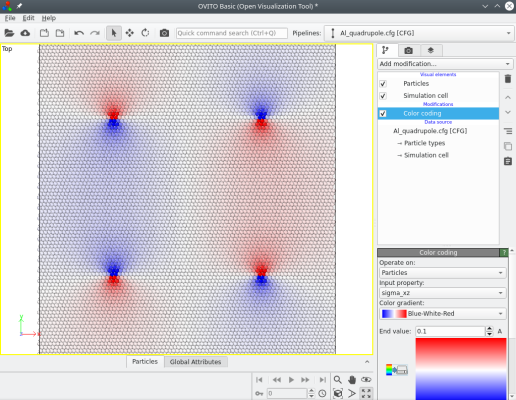
This time, at the border of the supercell, the displacements due to the four dislocations cancel out (because the sum of their Burgers vectors is naught). No boundary must be fixed, and 3-D periodic boundary conditions can be used.
Instead of having the dislocation line lying along the Cartesian Z axis, it may be desirable to align it with the X or Y axis. To do so, the initial unit cell has to be oriented differently, and the directions in the option "-dislocation" must also be modified. As an exercise, you may try to construct the same screw dislocation, but align it along the X or Y axis.
The screw dislocations constructed with the method above are not relaxed nor optimized. They correspond, at best, to the displacement fields predicted by the elastic theory of dislocations. However, in order to find the actual atomic configuration of the dislocation, the system needs to be optimized (e.g. by performing ab initio or atomistic simulations). For example, in the case of aluminium, it is expected that a ½[110] dislocation dissociates into two Shockley partial dislocations. Depending on the method chosen above, the dislocation interacts with frozen boundaries or with other dislocations, which can cause undesirable effects when performing a simulation. You may have to test different system sizes and different dislocation positions to make sure that your results are sound.
While this tutorial focuses on dislocations of pure screw character, it is also possible to construct dislocations of pure edge character with Atomsk, as explained in this tutorial.
By default the option "-dislocation" uses the displacement fields of isotropic elasticity. This is justified in the case of aluminium because it is an isotropic material. In materials that are highly anisotropic, it is recommended to use the anisotropic elasticity to introduce dislocations, as explained in the following tutorial.