Atomsk
The Swiss-army knife of atomic simulations

The Swiss-army knife of atomic simulations


In this tutorial, you will learn how to generate a grain boundary between two crystals, often referred to as a bicrystal. First we cover low-index grain boundaries, then symmetric grain boundaries with arbitrary rotations. Finally we will discuss the case of general grain boundaries.
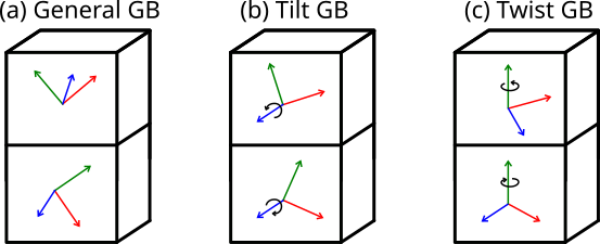
A grain boundary is the interface between two crystals, or crystallites, that differ in their crystallographic orientation. In the most general case the disorientation can be arbitrary, as illustrated in Fig. (a) below. When the two crystallites share a common rotation axis parallel to the grain boundary plane, like in Fig. (b), it is called a tilt grain boundary. When they share a common rotation axis normal to the grain boundary plane like in Fig. (c), it is called a twist grain boundary. When the rotation angles are exactly opposite, so that the two crystallites have the same periodicity in the grain boundary plane, then it is a symmetric grain boundary.
ⓘ Before using Atomsk, it is important to design your target system "on paper". Work out the crystal directions and/or rotations required to achieve your goal -otherwise Atomsk will be of no help.
To begin, consider two crystals of fcc aluminium that are rotated around their [001] axis, and then joined along their {210} planes. Note that on one side of this interface, it will be the (210) plane of a crystal, and on the other side it will be the (210) plane. Such a grain boundary is often referred to as a {210}[001] symmetric tilt grain boundary.
When the crystal directions are known, it is easiest to use the mode "--create" to generate crystals with the target orientations. Here we use Z=[001] as rotation axis, the normal to the grain boundary plane is Y=[210], and by deduction the third direction must be X=[120]:
atomsk --create fcc 4.046 Al orient [-120] [210] [001] crystal1.cfg
Now do the same for the second crystal, inverting the crystal direction along Y to Y=[210]:
atomsk --create fcc 4.046 Al orient [-120] [-2-10] [001] crystal2.cfg
Now we just have to stack the two crystals along the Y direction to form the bicrystal:
atomsk --merge Y 2 crystal1.cfg crystal2.cfg Al_210_001.cfg
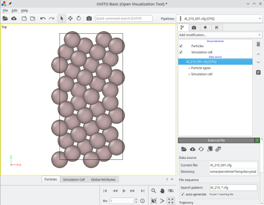
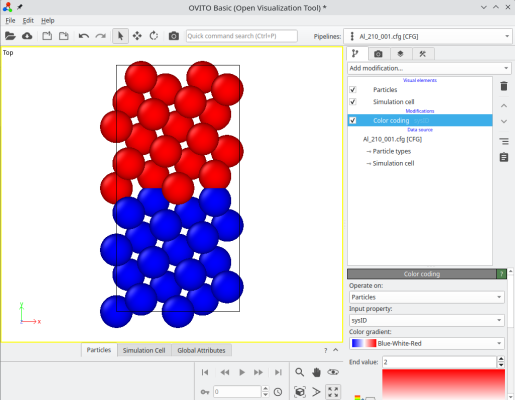
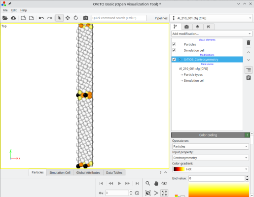
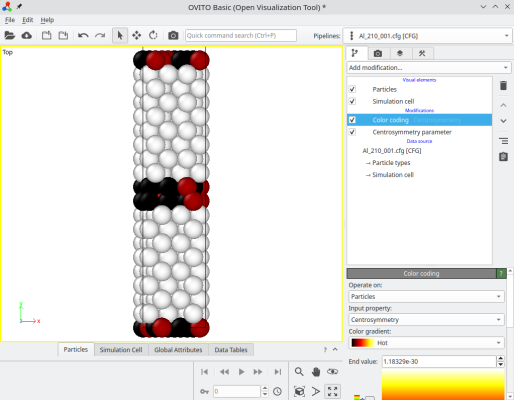
The final system can be visualized, for instance with OVITO. When merging systems, Atomsk creates a new auxiliary property called "sysID", indicating for each atom the index of the system it belonged to, in this case sysID=1 for crystal 1, and sysID=2 for system 2. This property "sysID" can be visualized using color coding (image at the center). Finally, you may also visualize defects using the centro-symmetry criterion, which allows to highlight the grain boundary.
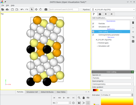
ⓘ By stacking the two grains, there exists a grain boundary at the center of the cell. If you use periodic boundary conditions (as is the case in OVITO), then the also exists another grain boundary at the edges of the simulation cell along Y (see coloured atoms at the top and bottom of the cell). For a symmetric tilt grain boundary in a cubic lattice, those two grain boundaries are equivalent. However, if the tilt is not symmetric, or if the lattice is not cubic, then the two grain boundaries may have different atomic structures, and therefore different properties.
Of course, this system is probably too small for practical purposes. The grain boundaries are too close to one another. To remedy this, you may simply use the option "-duplicate" when creating the initial crystals, for example if you wish to duplicate five times along Y, use the following commands:
atomsk --create fcc 4.046 Al orient [-120] [210] [001] -duplicate 1 5 1 crystal1.cfg
atomsk --create fcc 4.046 Al orient [-120] [-2-10] [001] -duplicate 1 5 1 crystal2.cfg
atomsk --merge Y 2 crystal1.cfg crystal2.cfg Al_210_001.cfg
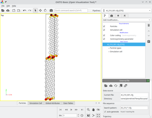
Now each grain is thicker along Y, so that the distance between the two grain boundaries is larger:
Depending on your purposes, you may also duplicate the system along the grain boundary plane directions X and Z. If you need to shift one grain with respect to the other, then during the merging operation, you can select atoms belonging to the second grain (sysID=2), and apply the "-shift" option:
atomsk --merge Y 2 crystal1.cfg crystal2.cfg Al_210_001.cfg -select prop sysID 2 -shift 4 0 0
Atoms of the second grain have been shifted as expected:
ⓘ You may append the option "-wrap" if you wish for all atoms to be inside the box.
To practice the commands above, you may try constructing different grain boundaries: {310}[001], {410}[001]. You may also try with different materials, for example with bcc Fe or with rock-salt MgO.
Now let us turn to another type, the twist grain boundary. This time, we place the [001] rotation axis along the Cartesian Y direction, and rotate the two crystals around it by opposite angles so the [210] axis of one grain is aligned with the [210] axis of the other. We also duplicate along Y to avoid small size effects:
atomsk --create fcc 4.046 Al orient [-120] [001] [210] -duplicate 1 5 1 crystal1.cfg
atomsk --create fcc 4.046 Al orient [-120] [001] [-2-10] -duplicate 1 5 1 crystal2.cfg
atomsk --merge Y 2 crystal1.cfg crystal2.cfg Al_twist_001.cfg
Again you may try with different crystal orientations, and with crystals of different lattices.
The previous sections described particular grain boundaries, corresponding to crystal directions with low Miller indices, like {210}, {310}, etc. What if instead, we want to rotate the crystals by an arbitrary angle α?
To construct a grain boundary with arbitrary misorientation, you can use the option "-rotate", and then the option "-orthogonal-cell". For example, to rotate the grains by ±5.1°:
atomsk --create fcc 4.046 Al -rotate Z 5.1 -orthogonal-cell crystal1.cfg
atomsk --create fcc 4.046 Al -rotate Z -5.1 -orthogonal-cell crystal2.cfg
atomsk --merge Y 2 crystal1.cfg crystal2.cfg Al_51.cfg
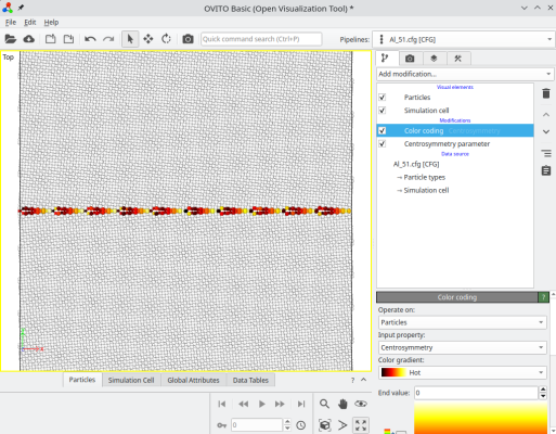
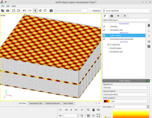
After rotating a crystal, the option "-orthogonal-cell" searches for linear combinations of the unit cell vectors, that produce new vectors aligned with the Cartesian X, Y, and Z directions. This ensures that the new cell vectors respect the periodicity of the lattice, so the system is periodic along X. However, sometimes this new orthogonal box is much larger than the original unit cell, in this example it is about 12,600 atoms. In this case, we constructed a symmetric tilt grain boundary, where each crystal is rotated by ±5.1°, resulting in a total misorientation of 10.2° between the grains. The final system can be visualized in OVITO:
ⓘ For some angles, or if the lattice is not cubic, it is possible that the option "-orthogonal-cell" fails to find suitable vectors.
To produce a twist grain boundary, the principle is the same, just rotate the system around Y instead. Only this time, we need to duplicate the system along Y:
atomsk --create fcc 4.046 Al -rotate Y 5.1 -orthogonal-cell -duplicate 1 10 1 crystal1.cfg
atomsk --create fcc 4.046 Al -rotate Y -5.1 -orthogonal-cell -duplicate 1 10 1 crystal2.cfg
atomsk --merge Y 2 crystal1.cfg crystal2.cfg Al_51.cfg
Depending on the rotation chosen, the systems constructed this way can be quite large.
With the methods presented above, it is quite simple to construct symmetric tilt or twist grain boundaries with any disorientation. However the construction is just a first step, be aware that these grain boundaries are not relaxed. One would have to run a simulation to find the minimum of energy. Often it is necessary to compute the energy with respect to the displacement of a grain (so-called γ-surface) to find the minimum (or minima) of energy.
To generate a polycrystal, i.e. a system containing multiple crystallites with different crystal orientations, proceed with the following tutorial.