Atomsk
The Swiss-army knife of atomic simulations

The Swiss-army knife of atomic simulations


This tutorial explains how to use Atomsk to create a half-sphere on a substrate, with the example of the copper-tantalum system.
Let us begin with the construction of the bcc tantalum substrate with a (110) surface. This part is quite easy: use the mode "--create" to generate a unit cell of bcc Ta with the appropriate orientation, along with the option "-duplicate" to generate a supercell.
atomsk --create bcc 3.31 Ta orient [1-10] [001] [110] \
-duplicate 40 60 10 bccTa_substrate.cfg
With this the (110) surface is normal to the Z axis. The supercell is written in "bccTa_substrate.cfg" and can be visualized:
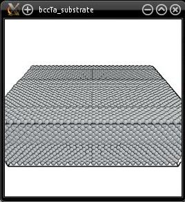
Note that right now, this box contains a 3-D periodic crystal of bcc Ta. It does not have free surfaces yet.
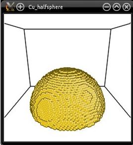
Now, let us construct the half-sphere of fcc copper. Say that we want a (111) surface of copper to meet the (110) surface of the Ta substrate. This can be achieved in the following way: create a unit cell of oriented copper (with the mode "--create"), duplicate it, then select atoms outside of a sphere and remove them:
atomsk --create fcc 3.61 Cu orient [11-2] [1-10] [111] \
-duplicate 40 60 20 \
-select out sphere 0.5*box 0.5*box 0.0 60 \
-rmatom select fccCu_halfsphere.cfg
Why does that work? In the option "-select", the center of the sphere is placed at Z=0. Since this option does not take periodic boundary conditions into account (it only considers the Cartesian coordinates of atoms), this actually selects half a sphere at the bottom of the supercell. The half-sphere looks like this:
Now we just have to stack the two systems on top of each other along the Z direction. This can be achieved with the mode "--merge":
atomsk --merge Z 2 bccTa_substrate.cfg fccCu_halfsphere.cfg CuTa_final.cfg
The "Z" means that the systems are stacked along the Z direction, and the "2" means that there are two systems to stack (which names follow). The final result is written in the file "CuTa_final.cfg":
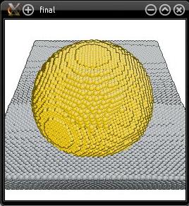
You may notice that the Cu half-sphere is not exactly at the center of the final cell. This is because we did not pay too much attention to the size of the boxes. Along the Z direction, the size of the final system is simply the sum of the sizes of the two sub-systems. However along X and Y, the final box has the same dimensions as the first box (i.e. the Ta substrate). If you swap the names of the files (i.e. if you use "--merge fccCu_halfsphere.cfg bccTa_substrate.cfg"), then the final system will have the same dimension as the Cu half-sphere system along X and Y, which is too small for the Ta substrate and would result in overlapping atoms. The order in which systems are merged is important for the size of the final system.
With the commands above we cut the Cu half-sphere in half, as a result it forms an angle of 90° with the substrate. Modifying this contact angle is rather straightforward: when cutting the Cu system, place the center of the selection sphere above or below Z=0. Placing it above Z=0 will result in an acute angle, while placing it below Z=0 will result in an obtuse angle. You may try it and verify for yourself.
Of course, you may also modify the commands above to change the size or thickness of the substrate, the radius of the sphere, its position, the crystal orientations of the substrate and sphere, and so on. You may also work with different elements and different lattices.
This tutorial illustrates that sometimes, you need to run Atomsk several times to achieve what you want. All systems cannot be created in a single command-line. Sometimes there exist no option to do what you want in one single step, so you have to use your imagination to achieve it in several steps. Atomsk can be used to create various systems separately, and then merge them into a final system. Here we used only three commands, but more complex systems may require more separate operations.